
Pouch cells represent a fundamental advancement in lithium-ion battery technology, offering superior energy density and flexible form factors for modern energy storage applications. These cells utilize a multi-layer aluminum laminate film enclosure instead of rigid metal casings, enabling lightweight construction and efficient space utilization.
Understanding pouch cell structure and manufacturing processes requires comprehensive knowledge of specialized equipment, material specifications, and quality control parameters. This guide examines the complete production workflow, from electrode preparation through final formation testing, with detailed technical specifications for each manufacturing stage.
What Equipment Does Pouch Cell Manufacturing Machine Production Require?
Pouch cell production demands precise coordination of multiple specialized machines operating within strict parameter tolerances. The manufacturing line encompasses electrode processing equipment, assembly systems, electrolyte filling stations, and formation testing units.
Essential equipment categories include electrode slitting machines for precise dimensional control, ultrasonic or resistance welding systems for tab attachment, stacking or winding equipment for cell assembly, and vacuum-based electrolyte filling systems. Each machine requires specific configuration based on cell dimensions, capacity targets, and production volume requirements.
Pouch Cell Structure and Component Specifications
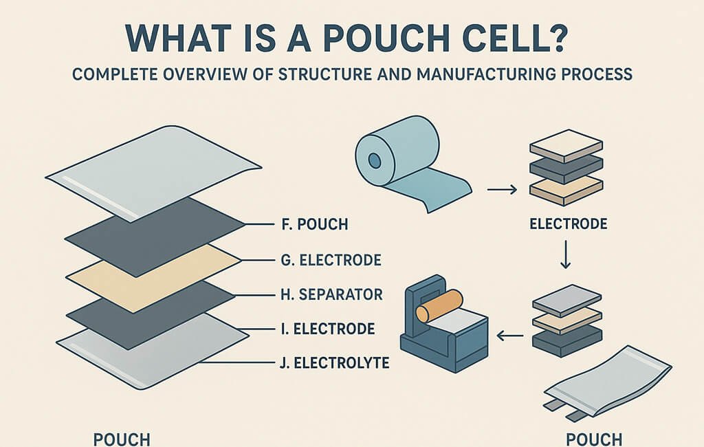
The pouch cell architecture consists of alternating positive and negative electrodes separated by polymer separators, housed within a flexible aluminum laminate pouch. This laminated structure typically comprises three layers: an outer nylon layer for mechanical protection, an aluminum foil barrier layer preventing moisture ingress, and an inner polypropylene layer enabling heat sealing.
Layer Configuration and Material Requirements
Standard pouch cells utilize electrode thicknesses ranging from 50-200 μm, with coating densities varying based on application requirements. The separator material, typically polyethylene or polypropylene, maintains 16-25 μm thickness with controlled porosity between 35-45%.
Tab materials include aluminum for positive terminals (0.1-0.3 mm thickness) and nickel or copper for negative terminals (0.1-0.2 mm thickness). The aluminum laminate film maintains total thickness between 88-153 μm, with specific layer distributions optimized for mechanical strength and barrier properties.
Manufacturing Process Flow and Equipment Parameters
The complete pouch cell manufacturing process encompasses multiple stages, each requiring specialized equipment with precise control parameters. Production begins with electrode preparation and concludes with formation cycling and quality verification.
Electrode Preparation Stage
Electrode slitting machines process coated foils into specified widths using either shear cutting or razor slitting methods. Shear cutting provides superior edge quality for thicker electrodes (>100 μm), while razor slitting offers advantages for thin, delicate materials.
| Parameter | Specification Range | Application Notes |
|---|---|---|
| Slit Width Tolerance | ±0.1 to ±0.3 mm | EV applications require ±0.1 mm; ESS allows ±0.3 mm |
| Web Tension | 20-80 N/m | Lower tension for delicate separators; higher for robust electrodes |
| Slitting Speed | 5-50 m/min | Speed varies with material thickness and edge quality requirements |
| Rewind Tension Taper | 10-30% reduction | Prevents telescoping in finished rolls |
| Edge Dust Extraction | >95% efficiency | Critical for preventing internal short circuits |
Tab Welding Process
Tab attachment utilizes either ultrasonic welding or resistance welding technologies. Ultrasonic systems operate at 20-40 kHz frequencies with welding forces between 100-500 N, achieving joint strengths exceeding 50 N pull force.
Resistance welding parameters include current densities of 200-800 A/mm², welding times of 10-50 ms, and electrode pressures of 0.2-0.8 MPa. Both methods require precise alignment control within ±0.5 mm to ensure consistent electrical connections.
How Does Cell Assembly Equipment Ensure Product Quality?
Cell assembly equipment incorporates multiple quality control mechanisms including vision systems for alignment verification, force sensors for stacking pressure monitoring, and contamination control through cleanroom integration. Stacking machines maintain positioning accuracy within ±0.2 mm while operating at speeds of 10-30 cells per minute.
Z-folding equipment provides continuous separator placement with tension control between 0.5-2.0 N, preventing separator wrinkles while maintaining proper electrode spacing. Automated inspection systems verify layer alignment, detect missing components, and identify contamination before pouch sealing.
Pouch Forming and Sealing Equipment
Vacuum forming machines shape aluminum laminate films into precise pocket geometries, accommodating cell stacks with minimal excess volume. Forming depths range from 3-20 mm depending on cell capacity, with corner radius control preventing stress concentration.
Heat sealing equipment operates at temperatures between 160-200°C with dwell times of 1-5 seconds. Sealing pressure ranges from 0.3-0.8 MPa, creating hermetic seals with peel strengths exceeding 15 N/15mm width.
Electrolyte Filling System Specifications
Electrolyte filling represents a critical process stage requiring precise volume control and environmental management. Vacuum filling systems operate at pressures below 100 Pa, removing trapped gases before electrolyte injection.
Filling Process Parameters
Standard filling equipment maintains electrolyte temperature control within ±2°C while dispensing volumes accurate to ±1% of target. Fill rates vary from 0.5-5.0 mL/s depending on cell size and electrolyte viscosity.
Post-filling vacuum degassing removes dissolved gases through pressure cycling between atmospheric and sub-100 Pa conditions. This process typically requires 3-5 cycles over 10-30 minutes, ensuring complete electrolyte penetration into electrode pores.
What Testing Parameters Verify Pouch Cell Quality?
Formation and testing equipment subjects completed cells to controlled charge-discharge cycles while monitoring voltage, current, temperature, and impedance parameters. Initial formation typically involves C/20 to C/10 charging rates with voltage accuracy of ±5 mV.
Testing protocols include capacity verification, internal resistance measurement, self-discharge evaluation, and mechanical integrity assessment. Automated grading systems sort cells into matching groups based on measured parameters, ensuring consistent battery pack performance.
Material Handling and Environmental Control
Pouch cell production requires stringent environmental controls maintaining humidity below 1% relative humidity (dew point below -45°C) in critical areas. Material handling systems incorporate nitrogen or dry air purging to prevent moisture absorption.
Electrode rolls utilize core diameters of 76-152 mm with maximum roll diameters reaching 500-800 mm. Automated guided vehicles (AGVs) transport materials between process stations while maintaining environmental isolation.
Cleanroom Classifications
Manufacturing areas maintain ISO Class 7-8 cleanliness levels (Class 10,000-100,000) with localized ISO Class 5-6 (Class 100-1,000) environments at critical assembly stations. Particle monitoring systems track 0.5 μm and 5.0 μm particle counts continuously.
Equipment Configuration for Different Cell Formats
Pouch cell manufacturing equipment accommodates various cell dimensions through modular tooling systems. Small consumer electronics cells (30-50 mm width) require different handling mechanisms than large-format EV cells (200-400 mm width).
Scalability Considerations
Production lines incorporate quick-change tooling for format flexibility, with changeover times typically ranging from 30 minutes to 4 hours depending on size differences. Servo-driven positioning systems enable programmable format changes without mechanical adjustments.
Multi-format capabilities require expanded parameter ranges: electrode thickness accommodation from 50-250 μm, separator width adjustment from 35-450 mm, and pouch pocket depths from 3-25 mm. Vision system flexibility ensures reliable operation across the entire size range.
Quality Control Integration Throughout Manufacturing
Modern pouch cell production lines integrate quality control at every process stage. In-line measurement systems monitor critical parameters continuously, enabling real-time process adjustment and defect prevention.
Key Quality Checkpoints
Electrode slitting incorporates laser measurement for width verification and edge quality assessment. Tab welding stations include pull-force testing on sample basis (typically 1 per 100-1000 welds) ensuring joint integrity.
Assembly equipment features vision-based inspection for component presence, alignment verification within ±0.2 mm tolerance, and contamination detection down to 0.5 mm particle size. Leak testing after sealing identifies defects using helium detection or pressure decay methods.
Common Manufacturing Defects and Troubleshooting
Understanding typical defect modes enables rapid troubleshooting and process optimization. The following checklist identifies common issues with corrective actions:
Electrode Processing Defects
- Edge burrs: Adjust blade sharpness, reduce slitting speed, optimize web tension
- Width variation: Calibrate positioning systems, verify blade alignment, check tension uniformity
- Telescoping: Implement tension taper control, reduce rewind speed, adjust lay-on roller pressure
- Coating damage: Lower web tension, inspect roller surfaces, verify knife clearance
Assembly and Sealing Issues
- Misalignment: Recalibrate vision systems, check fixture wear, verify servo positioning
- Weak seals: Adjust temperature/pressure/time parameters, inspect sealing bar surface, verify film quality
- Electrolyte leakage: Increase vacuum level, extend degassing time, optimize seal width
- Separator wrinkles: Adjust z-folding tension, check guide alignment, reduce feed speed
Technical Comparison of Cell Configurations
Manufacturing equipment selection depends significantly on target cell configuration. Each format presents unique advantages and equipment requirements:
| Aspect | Pouch Cell | Cylindrical Cell | Prismatic Cell |
|---|---|---|---|
| Energy Density | Highest (90-95% volume utilization) | Moderate (80-85% volume utilization) | High (85-90% volume utilization) |
| Manufacturing Complexity | Moderate (precision sealing required) | Low (established processes) | High (complex case forming) |
| Thermal Management | Excellent surface contact | Limited contact area | Good surface contact |
| Equipment Investment | Moderate | Low to moderate | High |
| Format Flexibility | Excellent | Limited | Moderate |
Conclusion
Pouch cell manufacturing requires precise coordination of specialized equipment operating within tight parameter tolerances. Success depends on understanding the complete process flow, from electrode preparation through final testing, while maintaining strict quality control at each stage.
Selecting appropriate pouch cell manufacturing machine systems demands careful evaluation of production requirements, quality standards, and future scalability needs. By implementing comprehensive process controls and maintaining equipment within specified parameters, manufacturers can achieve consistent product quality and optimal production efficiency.
Glossary
- Calendering
- Process of compressing electrode coatings to achieve target density and thickness using precision rollers
- Degassing
- Vacuum process removing dissolved gases from electrolyte after filling to prevent bubble formation
- Formation
- Initial charge-discharge cycling that creates the solid electrolyte interface (SEI) layer on electrodes
- Laminate Film
- Multi-layer aluminum composite material forming the flexible pouch enclosure
- Tab Welding
- Process of attaching current collector tabs to electrodes using ultrasonic or resistance welding
- Telescoping
- Lateral shifting of wound material layers causing uneven roll edges
- Web Tension
- Controlled pulling force applied to material during slitting and rewinding operations
- Z-folding
- Separator placement method creating continuous accordion-style folds between electrodes