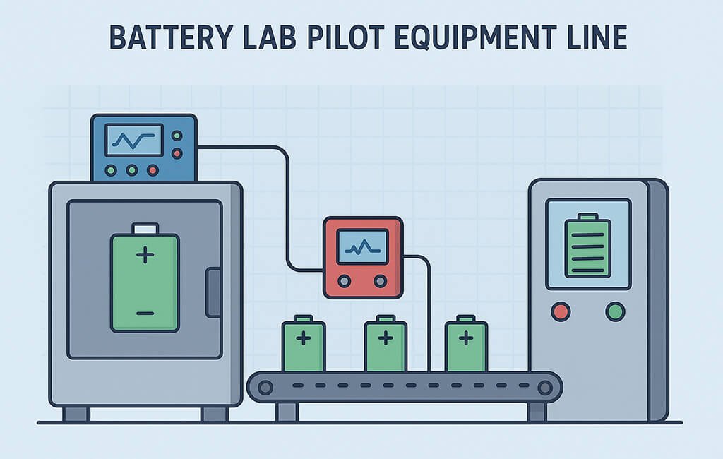
A battery lab pilot equipment line represents a scaled-down production system designed for research, development, and small-batch manufacturing of battery cells. These integrated systems bridge the gap between benchtop experiments and full-scale production, enabling manufacturers to validate processes, optimize parameters, and produce prototype cells for testing.
Understanding the components, workflow, and operational parameters of pilot lines has become essential as battery technology advances toward higher energy densities and novel chemistries. This guide examines the core equipment modules, process integration methods, and technical specifications that define modern pilot-scale battery production systems.
What Components Make Up a Battery Lab Pilot Equipment Line?
A complete pilot line integrates multiple process modules that mirror industrial-scale battery production. Each module performs specific operations while maintaining compatibility with upstream and downstream processes.
Electrode Preparation Systems
The electrode preparation section includes mixing, coating, calendering, and slitting equipment. Planetary mixers with 5-20 liter capacity blend active materials, binders, and conductive additives into homogeneous slurries. Coating machines apply these slurries onto current collectors using doctor blade or slot-die methods, achieving coating weights between 10-30 mg/cm².
Calendering presses compress coated electrodes to target porosity levels of 20-40%, enhancing energy density and electrical conductivity. Precision slitting machines cut electrodes to specified widths with tolerances of ±0.1mm, preparing materials for cell assembly.
Cell Assembly Equipment
Assembly modules handle electrode stacking, tab welding, and cell packaging operations. Semi-automatic stacking stations align electrodes and separators with positioning accuracy of ±0.5mm. Ultrasonic or resistance welding systems attach current collector tabs to electrodes, creating electrical connections with pull strengths exceeding 20N.
Packaging equipment varies by cell format. Pouch cell lines include aluminum laminate forming and sealing systems. Cylindrical lines incorporate winding machines and can insertion tools. Formation of the final cell package requires controlled environments with humidity levels below 1% RH.
Electrolyte Handling Systems
Electrolyte filling stations manage liquid electrolyte injection under controlled atmospheric conditions. Vacuum filling chambers evacuate cells to pressures below 100 Pa before introducing electrolyte, ensuring complete wetting of electrode structures. Dosing pumps deliver precise volumes with accuracies of ±0.5% across filling ranges from 1-1000 mL.
How Does Process Integration Work in Pilot Lines?
Effective pilot line operation requires seamless integration between individual process modules. Material handling systems, environmental controls, and data management infrastructure connect discrete operations into cohesive workflows.
Material Flow Configuration
Linear layouts arrange equipment sequentially from electrode preparation through final testing. This configuration minimizes material handling complexity and supports continuous process monitoring. Modular designs allow reconfiguration as process requirements evolve.
Buffer storage between process steps accommodates variations in cycle times. Climate-controlled storage maintains electrode moisture content below 200 ppm, preventing degradation during inter-process holding periods.
Environmental Control Systems
Dry rooms or gloveboxes maintain atmospheric conditions essential for lithium-ion cell assembly. Dew points below -40°C prevent moisture contamination of hygroscopic materials. HEPA filtration systems achieve ISO Class 7 cleanliness levels, reducing particulate contamination.
Temperature control systems maintain process zones within ±2°C of setpoints. This stability ensures consistent material properties and reaction kinetics throughout production sequences.
What Are the Key Process Parameters and Specifications?
Pilot line performance depends on precise control of multiple process variables. The following table summarizes critical parameters for major process steps:
| Process Step | Key Parameter | Typical Range | Application Notes |
|---|---|---|---|
| Electrode Coating | Coating Speed | 0.5-5 m/min | Higher speeds for EV applications; lower for ESS thick electrodes |
| Electrode Coating | Wet Thickness | 100-800 μm | CE devices: 100-200 μm; EV: 200-400 μm; ESS: 400-800 μm |
| Calendering | Line Pressure | 50-500 kN/m | Varies with electrode chemistry and target density |
| Slitting | Web Tension | 10-50 N | Lower tension for thin foils; higher for thick electrodes |
| Slitting | Cutting Speed | 5-30 m/min | Speed limited by edge quality requirements |
| Tab Welding | Welding Energy | 10-100 J | Ultrasonic: 10-30 J; Resistance: 50-100 J |
| Electrolyte Filling | Vacuum Level | 10-100 Pa | Lower pressure for high-viscosity electrolytes |
| Formation | C-rate | 0.05-0.5 C | Initial formation typically at 0.1 C or lower |
How Do Formation and Testing Systems Complete the Process?
Formation and testing equipment conditions newly assembled cells and validates their performance. These systems apply controlled charge-discharge cycles while monitoring voltage, current, and temperature responses.
Formation Process Requirements
Formation channels deliver precise current profiles during initial charging cycles. Current accuracy of ±0.05% ensures uniform solid electrolyte interface (SEI) formation. Temperature-controlled chambers maintain cells at 25-45°C during formation, optimizing SEI characteristics.
Multi-stage formation protocols adapt to different cell chemistries. Lithium-ion cells typically undergo 2-3 formation cycles at progressively higher currents. Data logging systems capture voltage profiles at 1-10 Hz sampling rates, enabling detailed analysis of formation kinetics.
Performance Testing Capabilities
Cycle testing stations evaluate cell capacity, efficiency, and lifetime. Programmable profiles simulate application-specific duty cycles. Rate capability tests apply currents from 0.1C to 10C, characterizing power performance.
Impedance spectroscopy equipment measures internal resistance across frequency ranges from 0.01 Hz to 100 kHz. These measurements detect manufacturing defects and predict long-term performance degradation.
What Are Common Troubleshooting Challenges in Pilot Line Operation?
Pilot line operators encounter various technical challenges that require systematic troubleshooting approaches. The following checklist addresses frequent issues:
Electrode Processing Issues
- □ Coating thickness variations: Check blade gap uniformity, substrate tension, and slurry viscosity stability
- □ Edge defects: Verify blade condition, adjust edge guides, and optimize coating speed
- □ Calendering non-uniformity: Inspect roll parallelism, check bearing conditions, and validate pressure distribution
- □ Slitting burrs: Replace cutting blades, adjust blade clearance, and verify web tension consistency
- □ Material delamination: Review binder content, optimize drying parameters, and check calendering pressure
Assembly and Filling Problems
- □ Alignment errors: Calibrate vision systems, check fixture tolerances, and verify material dimensions
- □ Weak welds: Adjust welding parameters, clean electrode surfaces, and inspect tooling condition
- □ Incomplete electrolyte wetting: Extend vacuum time, increase fill temperature, and verify electrolyte composition
- □ Seal failures: Check sealing temperature and pressure, inspect seal bar alignment, and verify pouch material quality
How Do Different Configuration Options Compare?
Pilot lines offer various configuration options to match specific research and production requirements. Understanding these alternatives helps optimize system selection and utilization.
Process Integration Methods
| Configuration | Characteristics | Advantages | Limitations |
|---|---|---|---|
| Fully Integrated | All processes in single environment | Minimal contamination risk; automated material transfer | High initial investment; limited flexibility |
| Modular Stations | Separate equipment with manual transfer | Process flexibility; lower cost; easy reconfiguration | Higher contamination risk; labor intensive |
| Hybrid Systems | Critical processes integrated; others standalone | Balanced cost and performance; selective automation | Complex interfaces; mixed training requirements |
Scale and Throughput Options
Laboratory-scale systems process 10-100 cells per day, supporting early-stage research and parameter optimization. Pilot-scale configurations achieve 100-1000 cells daily, enabling statistically significant testing and customer sampling.
Pre-production lines reach 1000-10,000 cells per day, validating manufacturing processes before full-scale implementation. Equipment sizing, automation level, and process speeds scale accordingly across these capacity ranges.
What Standards and Validation Protocols Apply?
Pilot line operations follow established standards ensuring reproducible results and scalable processes. ISO 9001 quality management principles guide documentation and process control procedures.
Equipment Qualification
Installation Qualification (IQ) verifies proper equipment setup according to manufacturer specifications. Operational Qualification (OQ) confirms equipment performs within defined parameters across its operating range.
Performance Qualification (PQ) demonstrates consistent production of cells meeting target specifications. Statistical process control methods track critical quality attributes including capacity, impedance, and dimensional tolerances.
Safety and Environmental Compliance
Pilot facilities implement safety protocols addressing chemical hazards, electrical risks, and mechanical dangers. Material Safety Data Sheets guide handling procedures for electrode materials and electrolytes.
Environmental controls manage volatile organic compound emissions from coating processes. Solvent recovery systems capture and recycle NMP or other coating solvents, minimizing environmental impact.
Conclusion
A battery lab pilot equipment line integrates specialized machinery for electrode preparation, cell assembly, electrolyte filling, and formation testing into a cohesive production system. These pilot-scale facilities enable battery developers to transition from laboratory concepts to manufacturable products while optimizing process parameters and validating quality control methods.
Success with pilot line operations requires understanding equipment capabilities, maintaining precise environmental controls, and implementing systematic troubleshooting approaches. As battery technologies continue evolving, pilot lines provide the essential platform for innovation, process development, and manufacturing readiness across emerging cell chemistries and formats.
Glossary
- Calendering
- Process of compressing coated electrodes between rollers to achieve target density and thickness uniformity
- Doctor Blade
- Precision metering device that controls coating thickness by maintaining fixed gap above substrate
- Formation
- Initial charging process that creates protective solid electrolyte interface layer on electrode surfaces
- C-rate
- Charge or discharge current normalized to cell capacity; 1C fully charges/discharges cell in one hour
- Dry Room
- Controlled environment maintaining moisture levels below -40°C dew point for moisture-sensitive battery materials
- Tab Welding
- Process of attaching metal current collector tabs to electrodes using ultrasonic or resistance welding methods
- Slitting
- Precision cutting operation that converts wide electrode webs into strips of specified width
- SEI Layer
- Solid electrolyte interface formed during initial charging; critical for battery stability and cycle life