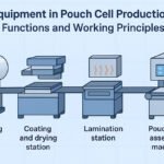

Battery cell manufacturing equipment varies significantly based on the chosen cell format. Each configuration—pouch, prismatic, and cylindrical—demands specific machinery adaptations and process parameters.
Understanding these differences enables manufacturers to select appropriate equipment configurations and optimize production lines for their target applications.
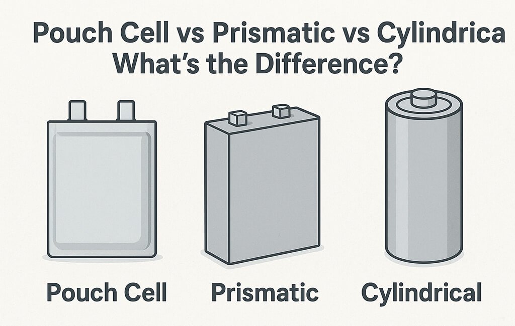
What are the key manufacturing equipment differences between pouch, prismatic, and cylindrical cells?
Pouch cells require heat sealing systems and flat stacking equipment, while prismatic cells need laser welding stations and rigid case assembly lines. Cylindrical cells utilize winding machines and crimping systems for their unique geometry.
Manufacturing Equipment Specifications by Cell Format
| Process Stage | Pouch Cell Equipment | Prismatic Cell Equipment | Cylindrical Cell Equipment | Key Parameters |
|---|---|---|---|---|
| Electrode Processing | Z-fold stacking machine | Flat stacking system | Continuous winding machine | Alignment: ±0.5mm; Speed: 20-60 layers/min |
| Tab Welding | Ultrasonic welder (20-40 kHz) | Laser welder (1064nm) | Resistance spot welder | Weld strength: >30N; Contact resistance: <0.5mΩ |
| Cell Assembly | Vacuum sealing chamber | Case insertion system | Can insertion & grooving | Vacuum level: <100Pa; Insertion force: 50-200N |
| Electrolyte Filling | Vacuum filling (top/side) | Precision dosing system | High-speed injection | Fill accuracy: ±0.5%; Vacuum: <10Pa |
| Sealing | Heat sealing bars (180-220°C) | Laser welding head | Crimping die set | Seal integrity: <10⁻⁶ mbar·L/s |
| Formation | Compression fixtures | Standard channels | Spring-loaded contacts | Current accuracy: ±0.05%; Voltage: ±0.02% |
The equipment selection directly impacts production throughput and quality control parameters. Each format presents unique challenges in maintaining dimensional tolerances and ensuring consistent performance.
Electrode Assembly Methods and Equipment Configuration
Stacking Systems for Pouch and Prismatic Cells
Pouch cell manufacturing machines employ Z-folding or discrete stacking methods. The Z-fold configuration uses a continuous separator web with alternating anode and cathode placement, achieving speeds of 40-60 layers per minute.
Discrete stacking systems handle individual electrode sheets, providing flexibility for varying cell capacities. Vision systems ensure ±0.3mm alignment accuracy between layers.
Key stacking parameters include:
– Electrode tension control: 0.5-2.0 N
– Separator tension: 0.3-1.0 N
– Stacking pressure: 0.1-0.5 MPa
– Environmental control: <1% RH, Class 1000 cleanroom
Winding Systems for Cylindrical Cells
Cylindrical cell production utilizes continuous winding machines operating at 5-20 m/min. The winding tension must maintain consistent pressure without damaging the electrode coating.
Winding specifications include:
– Mandrel diameter: 3-10mm (application dependent)
– Tension gradient: 10-30% reduction from start to finish
– Winding angle: 90° ±0.5°
– Edge alignment: ±0.2mm
How do tab welding requirements differ between cell formats?
Pouch cells use ultrasonic welding for aluminum and nickel tabs, requiring 20-40 kHz frequency and 50-200N pressure. Prismatic cells employ laser welding for thicker tabs, while cylindrical cells need resistance welding for can-to-tab connections with precise current control.
Tab Welding Process Parameters
Tab attachment represents a critical quality control point. Each welding method requires specific parameter optimization based on material thickness and composition.
Ultrasonic welding parameters for pouch cells:
– Frequency: 20-40 kHz
– Amplitude: 20-60 μm
– Welding time: 0.1-0.5 seconds
– Hold time: 0.2-1.0 seconds
Laser welding parameters for prismatic cells:
– Power: 1-4 kW
– Pulse duration: 2-10 ms
– Spot size: 0.3-1.0 mm
– Shield gas flow: 15-25 L/min
Electrolyte Filling Equipment Variations
Electrolyte dispensing systems adapt to each cell geometry’s requirements. The filling process must prevent air entrapment while ensuring complete wetting of all electrode surfaces.
Vacuum Filling for Pouch Cells
Pouch cell filling stations incorporate dual-stage vacuum systems. Initial evacuation reaches <100 Pa, followed by electrolyte injection under maintained vacuum conditions.
Filling sequence parameters:
– Pre-vacuum time: 30-120 seconds
– Vacuum level: <50 Pa – Fill rate: 5-50 mL/min – Post-fill vacuum hold: 60-300 seconds
Precision Dosing for Prismatic Cells
Prismatic cells utilize volumetric or gravimetric dosing systems. The rigid case structure allows for faster filling rates compared to flexible pouch formats.
Dosing specifications:
– Volume accuracy: ±0.5%
– Fill rate: 20-200 mL/min
– Temperature control: ±2°C
– Moisture content monitoring: <20 ppm
High-Speed Injection for Cylindrical Cells
Cylindrical cell filling employs needle injection systems optimized for the narrow opening. Multi-stage filling prevents electrolyte overflow and ensures proper distribution.
Injection parameters:
– Needle diameter: 1.5-3.0 mm
– Injection pressure: 0.2-0.8 MPa
– Fill stages: 2-4 cycles
– Penetration depth: 50-80% of can height
Sealing Technology Requirements by Format
Cell sealing methods directly correspond to the housing material and geometry. Each technique requires specialized equipment and process control systems.
Heat Sealing Systems for Pouch Cells
Pouch cell manufacturing machines incorporate impulse or constant-heat sealing bars. The sealing process must accommodate the multilayer aluminum laminate film structure.
Heat sealing specifications:
– Temperature range: 160-220°C
– Pressure: 0.3-1.0 MPa
– Dwell time: 2-8 seconds
– Cooling time: 3-10 seconds
Critical sealing parameters include temperature uniformity (±3°C) across the sealing bar and pressure distribution (<5% variation).
Laser Welding for Prismatic Cells
Prismatic cell cases require laser welding systems with precision beam control. The welding process must achieve hermetic seals without damaging internal components.
Laser welding parameters:
– Beam power: 2-6 kW
– Welding speed: 2-10 m/min
– Focus position: -1 to +2 mm
– Overlap ratio: 30-50%
Crimping Systems for Cylindrical Cells
Cylindrical cells employ mechanical crimping with precise force control. The crimping die geometry must match the specific cell diameter and case thickness.
Crimping specifications:
– Force range: 5-50 kN
– Die tolerance: ±0.02 mm
– Crimp depth: 1.5-3.0 mm
– Cycle time: 1-3 seconds
What are the formation and testing equipment differences?
Pouch cells require compression fixtures during formation to prevent swelling, applying 0.1-0.3 MPa pressure. Prismatic cells use standard channel configurations, while cylindrical cells need spring-loaded contacts to accommodate dimensional changes during cycling.
Formation Equipment Configuration
Formation systems must accommodate the physical constraints and thermal management requirements of each cell format.
Pouch cell formation fixtures:
– Compression plates with uniform pressure distribution
– Temperature monitoring at multiple points
– Adjustable spacing for different thicknesses
– Integrated safety pressure relief
Channel specifications for all formats:
– Current range: 0.1-100 A
– Voltage range: 0-5 V
– Current accuracy: ±0.05% of full scale
– Voltage accuracy: ±0.02% of full scale
– Temperature monitoring: ±0.5°C
Testing Equipment Adaptations
End-of-line testing equipment incorporates format-specific fixtures and connection systems. Each configuration requires unique approaches to ensure reliable electrical contact and accurate measurements.
Testing parameters include:
– Internal resistance: <0.1 mΩ resolution – Capacity measurement: ±0.1% accuracy – Voltage retention: >99.5% after 24 hours
– Leakage current: <10 μA threshold
Quality Control and Inspection Systems
Manufacturing equipment must integrate inspection systems tailored to each cell format’s critical quality attributes.
Dimensional Inspection
Pouch cells require thickness monitoring throughout production, with typical tolerances of ±0.1 mm. Laser displacement sensors or contact measurement systems track thickness variations.
Prismatic cells need case dimension verification:
– Length/width: ±0.2 mm
– Height: ±0.3 mm
– Squareness: <0.5° – Surface flatness: <0.2 mm
Cylindrical cells require diameter and height checks:
– Diameter: ±0.1 mm
– Height: ±0.2 mm
– Concentricity: <0.1 mm – Bottom crimp integrity
Leak Detection Methods
Each cell format employs different leak detection approaches based on their sealing methods and housing materials.
Pouch cell leak testing:
– Vacuum decay method
– Pressure range: 50-500 mbar
– Test duration: 10-60 seconds
– Rejection threshold: >0.1 mbar pressure change
Prismatic and cylindrical leak testing:
– Helium leak detection
– Sensitivity: 10⁻⁶ to 10⁻⁸ mbar·L/s
– Background suppression required
– Calibration frequency: Every 8 hours
Troubleshooting Guide for Cell Manufacturing Equipment
Common Issues and Solutions
| Issue | Pouch Cell Equipment | Prismatic Cell Equipment | Cylindrical Cell Equipment |
|---|---|---|---|
| Electrode Misalignment | Check stacking vision system calibration; verify separator tension | Adjust pick-and-place vacuum levels; clean alignment pins | Calibrate winding tension; check mandrel concentricity |
| Poor Weld Quality | Verify ultrasonic horn parallelism; check amplitude settings | Clean laser optics; adjust focal position | Replace welding electrodes; verify current waveform |
| Electrolyte Leakage | Increase sealing temperature/time; check film cleanliness | Verify laser power stability; inspect weld penetration | Adjust crimping force; inspect die wear |
| Formation Issues | Check compression uniformity; verify contact resistance | Clean connection points; verify channel calibration | Replace worn spring contacts; check contact pressure |
| Dimension Variations | Monitor stacking pressure consistency; check fixture wear | Verify case supplier tolerances; adjust insertion force | Calibrate winding tension control; check material thickness |
Equipment Configuration and Changeover Considerations
Manufacturing flexibility often requires equipment capable of handling multiple cell formats or sizes within a format category.
Tooling Changeover Requirements
Pouch cell equipment changeovers:
– Stacking fixture replacement: 30-60 minutes
– Sealing bar adjustment: 15-30 minutes
– Formation fixture changes: 45-90 minutes
– Vision system reprogramming: 10-20 minutes
Prismatic cell equipment adjustments:
– Case handling gripper changes: 20-40 minutes
– Welding fixture replacement: 60-120 minutes
– Filling needle positioning: 10-15 minutes
– Testing contact reconfiguration: 30-45 minutes
Cylindrical cell line modifications:
– Winding mandrel replacement: 15-25 minutes
– Can feeder adjustment: 20-30 minutes
– Crimping die changeover: 45-60 minutes
– Formation contact spacing: 10-15 minutes
Process Parameter Optimization
Each format change requires systematic parameter adjustment and validation. Documentation systems must track parameter sets for different product configurations.
Critical parameters requiring adjustment:
– Material feed rates and tensions
– Welding energy and timing
– Filling volumes and rates
– Sealing/crimping forces
– Formation current profiles
– Quality control thresholds
Cleanliness Standards and Environmental Control
Battery manufacturing equipment operates within controlled environments to prevent contamination and ensure product quality.
Cleanroom Classifications by Process Area
Electrode handling areas:
– ISO Class 7 (Class 10,000) minimum
– Humidity control: <1% RH – Temperature: 20-25°C ±2°C – Positive pressure differential: 10-15 Pa
Cell assembly zones:
– ISO Class 6 (Class 1,000) for open cell operations
– Dew point: < -40°C – Particle monitoring: 0.5 μm and 5.0 μm sizes – Personnel protocol: Full bunny suits required
Equipment Design for Cleanliness
Manufacturing equipment incorporates features to minimize particle generation and facilitate cleaning procedures.
Design considerations:
– Stainless steel construction with electropolished surfaces
– Sealed bearings and drives
– Laminar flow integration points
– Quick-disconnect systems for maintenance
– HEPA filtration on pneumatic exhausts
Conclusion
Selecting appropriate pouch cell manufacturing machine configurations requires understanding the fundamental differences between cell formats. Each type—pouch, prismatic, and cylindrical—demands specific equipment adaptations for electrode assembly, tab welding, electrolyte filling, and sealing operations.
Successful implementation depends on matching equipment specifications to product requirements while maintaining flexibility for future needs. Proper attention to process parameters, quality control systems, and environmental conditions ensures consistent production output regardless of the chosen cell format.
Glossary
- Z-folding
- Continuous separator winding method with alternating electrode placement used in pouch cell stacking systems
- Ultrasonic welding
- High-frequency vibration joining method for connecting tabs to current collectors in pouch cells
- Vacuum decay testing
- Leak detection method measuring pressure change over time in sealed chamber
- Formation
- Initial charge-discharge cycling process that creates the solid electrolyte interface layer
- Dew point
- Temperature at which moisture condenses from air, critical parameter for battery assembly environments
- Crimping
- Mechanical deformation process used to seal cylindrical cell cases
- Tab
- Metal strip connecting electrode to external terminal, requiring precise welding control
- Impulse sealing
- Heat sealing method using short duration high-temperature pulse for pouch cell closure