
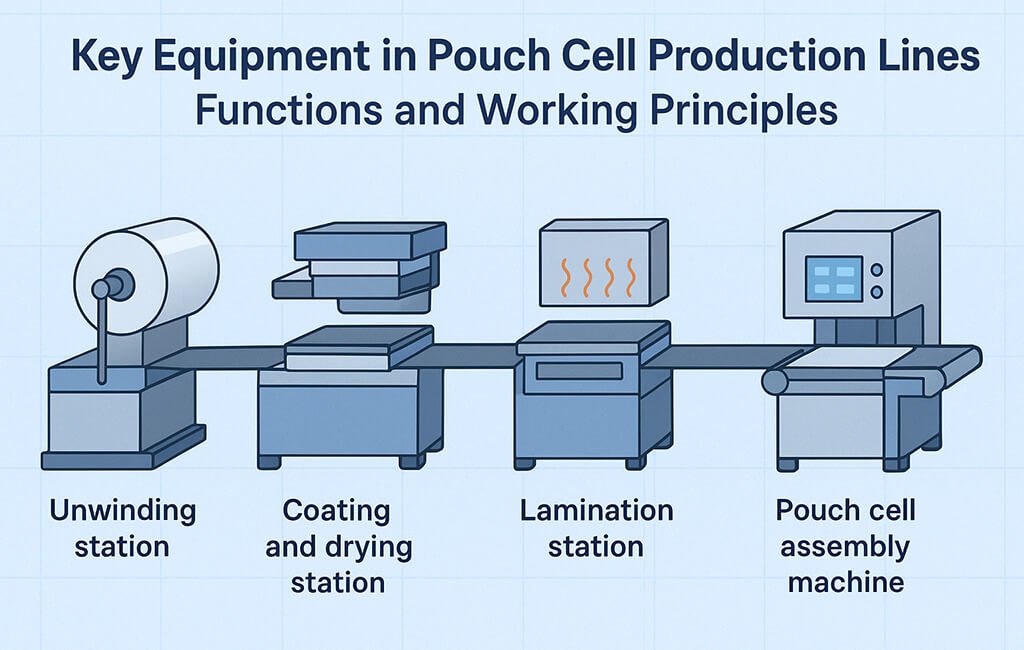
Pouch cell manufacturing machine systems represent the backbone of modern lithium-ion battery production, integrating precision equipment across electrode preparation, cell assembly, electrolyte filling, and formation processes. Each equipment station performs critical functions that directly impact cell performance, safety, and production yield.
This guide examines the essential equipment categories in pouch cell production lines, detailing their operational principles, key specifications, and integration requirements for automotive, energy storage, and consumer electronics applications.
What Are the Primary Pouch Cell Manufacturing Machine Categories?
Pouch cell production lines comprise five main equipment categories: electrode processing systems, tab welding stations, pouch assembly equipment, electrolyte filling systems, and formation/testing units. Each category contains specialized machinery designed to meet precise tolerances and process requirements.
The equipment selection and configuration depend on cell format, capacity requirements, and production volume targets.
Electrode Processing Equipment
Slitting Machines
Electrode slitting machines convert master rolls of coated electrode material into precise width strips for individual cells. These systems employ either rotary shear or razor blade cutting mechanisms, with selection based on coating thickness and material properties.
Modern slitting equipment incorporates tension control systems maintaining 0.5-2.0 N/cm across the web width. This prevents material deformation while ensuring clean edge quality.
Key operational parameters include:
| Parameter | Specification Range | Application Notes |
|---|---|---|
| Slit Width Tolerance | ±0.05 to ±0.1 mm | Tighter tolerance for automotive applications |
| Line Speed | 10-60 m/min | Lower speeds for thicker electrodes |
| Web Tension | 0.5-2.0 N/cm | Material-dependent optimization |
| Edge Dust Generation | <50 particles/m² | Critical for high-energy cells |
| Rewind Tension Taper | 10-30% reduction | Prevents telescoping in storage |
Die Cutting Systems
Die cutting equipment produces individual electrode sheets with integrated tab extensions. These systems utilize precision-ground steel rule dies or rotary cutting mechanisms.
Critical control features include vacuum hold-down tables maintaining <0.1mm flatness and automated vision systems for alignment verification. Die wear monitoring prevents edge quality degradation.
Notching Machines
Notching equipment creates precise tab geometries on continuous electrode webs. The process removes active material while preserving current collector integrity for electrical connections.
Laser notching systems offer advantages for complex geometries, while mechanical punching provides higher throughput for standard designs. Both methods require dust extraction systems to prevent contamination.
How Do Tab Welding Systems Ensure Connection Reliability?
Tab welding equipment creates electrical connections between electrode current collectors and external terminals through ultrasonic or laser welding processes. These systems must accommodate dissimilar metal joining while maintaining minimal contact resistance.
Process control parameters include weld energy, pressure profiles, and anvil temperature management for consistent joint quality.
Ultrasonic Welding Configuration
Ultrasonic tab welding applies high-frequency vibrations (20-40 kHz) to create solid-state bonds between aluminum and copper components. The process generates minimal heat affected zones, preserving electrode coating integrity.
Key system components include:
- Piezoelectric transducers with 1-3 kW power ratings
- Amplitude boosters providing 20-60 μm displacement
- Pneumatic actuators delivering 100-500 N weld force
- Anvil designs specific to tab geometry and thickness
Laser Welding Systems
Laser welding equipment offers non-contact joining for thick tab assemblies or multiple layer configurations. Fiber laser sources (1-3 kW) provide precise energy control with minimal thermal input.
Beam delivery systems incorporate galvanometer scanners for rapid positioning and wobble patterns that enhance joint strength. Shielding gas management prevents oxidation during welding.
Pouch Assembly Equipment
Stacking Machines
Automated stacking equipment assembles alternating layers of anode, separator, and cathode materials into cell stacks. These systems employ vacuum grippers or mechanical clamps for material handling.
Position accuracy requirements typically reach ±0.2 mm for automotive cells, with vision systems verifying alignment before each layer placement. Separator tension control prevents wrinkles that could cause internal shorts.
Pouch Forming and Sealing
Pouch forming equipment shapes aluminum laminate film into cell enclosures through deep drawing or folding processes. Heat sealing stations create hermetic seals along pouch edges.
Critical parameters include:
- Sealing temperature: 160-200°C
- Dwell time: 2-5 seconds
- Pressure: 0.3-0.8 MPa
- Seal width: 5-10 mm
Pre-sealing Stations
Pre-sealing equipment creates temporary closures before electrolyte filling, leaving designated injection ports open. These systems maintain controlled atmospheres to minimize moisture exposure.
What Electrolyte Filling Methods Optimize Cell Performance?
Electrolyte filling systems introduce liquid electrolyte into assembled cells through vacuum or pressure-assisted methods. Equipment design must prevent air entrapment while ensuring complete wetting of electrode surfaces.
Modern filling stations incorporate multi-stage processes with intermediate vacuum cycles for optimal penetration.
Vacuum Filling Systems
Vacuum filling equipment operates by evacuating air from sealed chambers containing open cells. Electrolyte injection occurs under reduced pressure, enhancing penetration into porous electrode structures.
Process stages typically include:
- Initial evacuation to 10-100 Pa
- Electrolyte injection at controlled flow rates
- Pressure cycling for enhanced wetting
- Final vacuum hold for degassing
Pressure-Assisted Filling
Pressure filling systems apply controlled overpressure (0.1-0.3 MPa) to accelerate electrolyte penetration. This method suits high-viscosity electrolytes or cells with dense electrode structures.
Equipment features include precision metering pumps, pressure vessels rated for electrolyte compatibility, and automated valve systems for process control.
Formation and Testing Equipment
Formation Cycling Systems
Formation equipment performs initial charge-discharge cycles that establish the solid electrolyte interface (SEI) layer. These systems provide precise current and voltage control across multiple channels.
Channel specifications for modern formation equipment include:
- Current accuracy: ±0.05% of full scale
- Voltage accuracy: ±0.02% of full scale
- Temperature monitoring: ±0.5°C
- Data logging rates: 10-100 Hz
Testing and Grading Systems
Final testing equipment evaluates cell capacity, internal resistance, and self-discharge characteristics. Automated handling systems sort cells into performance grades.
Test protocols incorporate industry standards including IEC 62133 for safety evaluation and ISO 12405 for automotive applications. Data management systems track individual cell performance through unique identifiers.
Process Integration and Control Systems
Material Handling Automation
Automated guided vehicles (AGVs) and conveyor systems transport materials between production stations. These systems maintain controlled environments while minimizing manual handling.
Integration requirements include:
- Clean room compatibility (ISO 7 or better)
- ESD protection for sensitive components
- Traceability through RFID or barcode systems
- Interface with manufacturing execution systems (MES)
Quality Control Integration
In-line inspection equipment monitors critical parameters throughout the production process. Vision systems detect defects in electrode coating, tab placement, and seal integrity.
Statistical process control (SPC) software analyzes trending data to identify process drift before specification limits are exceeded. Automated feedback loops adjust equipment parameters based on measurement results.
Equipment Configuration Considerations
Method Comparison Table
| Process | Method Option 1 | Method Option 2 | Selection Criteria |
|---|---|---|---|
| Electrode Cutting | Rotary Shear | Laser Cutting | Throughput vs. edge quality |
| Tab Welding | Ultrasonic | Laser | Material thickness and accessibility |
| Electrolyte Filling | Vacuum | Pressure | Electrolyte viscosity and cell design |
| Formation | Individual Channel | Parallel Groups | Flexibility vs. capital efficiency |
Troubleshooting Checklist
Common equipment issues and diagnostic approaches:
- ☐ Electrode edge burrs: Check blade sharpness, adjust cutting parameters, verify material tension
- ☐ Tab weld failures: Confirm surface cleanliness, calibrate weld energy, inspect tooling wear
- ☐ Incomplete electrolyte filling: Verify vacuum levels, check for seal leaks, adjust filling time
- ☐ Formation capacity variation: Calibrate current sources, verify temperature uniformity, check contact resistance
- ☐ Pouch seal leaks: Adjust temperature/pressure/time parameters, inspect seal bar alignment
- ☐ Stacking misalignment: Calibrate vision systems, check gripper positioning, verify material dimensions
Standards and Compliance Requirements
Pouch cell manufacturing equipment must comply with relevant safety and quality standards. Key requirements include:
- IEC 62133-2: Safety requirements for portable sealed secondary cells
- UN 38.3: Transportation testing for lithium batteries
- ISO 12405-4: Test specifications for lithium-ion traction battery systems
- UL 1642: Safety standards for lithium batteries
Equipment qualification protocols verify compliance through installation qualification (IQ), operational qualification (OQ), and performance qualification (PQ) procedures.
Maintenance and Calibration Programs
Preventive maintenance schedules ensure consistent equipment performance. Critical maintenance activities include:
- Daily: Visual inspections, cleaning, lubrication checks
- Weekly: Calibration verification, tool wear assessment
- Monthly: Deep cleaning, component replacement per wear indicators
- Annual: Major overhauls, control system updates
Calibration intervals follow equipment manufacturer recommendations and quality system requirements. Documentation systems track all maintenance activities for audit compliance.
Conclusion
Pouch cell manufacturing machine systems form an integrated production ecosystem where each equipment category contributes critical functionality to the final product quality. Understanding the working principles, specifications, and integration requirements of these systems enables informed decisions for production line design and optimization.
Success in pouch cell manufacturing depends on careful equipment selection, rigorous process control, and systematic maintenance programs that ensure consistent performance across all production stages.
Glossary
- Current Collector
- Metal foil (aluminum for cathode, copper for anode) that conducts electrons to and from the active material
- SEI Layer
- Solid Electrolyte Interface – protective layer formed on anode surface during initial charging cycles
- Tab Welding
- Process of joining current collector extensions to external terminals using ultrasonic or laser energy
- Vacuum Filling
- Electrolyte injection method using reduced pressure to enhance penetration into electrode pores
- Formation Cycling
- Initial charge-discharge process that activates the cell and establishes stable electrochemical interfaces
- Deep Drawing
- Metal forming process used to create three-dimensional pouch shapes from flat aluminum laminate
- Telescoping
- Lateral shifting of wound electrode layers causing misalignment and potential short circuits
- Edge Burr
- Raised material along cut edges that can penetrate separators and cause internal shorts